
Brute Force Atmospheric Path Tracer
Building a physically based atmospheric renderer without precomputation

![]() Radiance at distance x in direction ω (1)
Radiance at distance x in direction ω (1)
In the last part we covered how to sample a procedural sky. Today we are going to take a look at , in what context these sampling technique is used. We will also go over topics of how to light a volume and how transmittance effects lighting.
To be able to understand lighting in it’s complete context, we will also cover phase functions and their effects on lighting.
Before you go any further it’s advised that you take a look at “Direct Lighting” in pbrt.
Now please take a look at the equation on top of this page. It explains almost everything we will be covering today. What it basically means that, the light that a point recieves in direction ω at a distance x, is found by integrating transmittance to a distance D and multiplying that by the total light that point receives from all directions in a sphere ( Ω4π) based on a phase function.
Now let’s go over them one by one.
If you step into the world of volumetric rendering, you will hear the term transmittance a lot. What it basically represents is the fraction of some kind of energy (photons, neutrons, gamma rays… you name it) proportional to a point at the source of that emitter. So it’s very reasonable to think of transmittance as visibility. If you are in space and look at a light source you receive %100 of it. And by chance if there is a volumetric object between you, like a nebula, the light you receive gets less based on a mathematical formulae Beer-Lambert. You can see this formulae in the first part of the integral: the transmittance decreases exponentially based on volumes extinction attribute.
Calculating transmittance is very easy if the volume is homogenous (density is same everywhere in infinite dimensions or in a bounding box). But very laborous if the density is changing based on your 3D position.
To calculate the transmittance I’m using the “ratio tracking” algorithm from pbrt with a minor difference. I’ve also added a transmittance depth parameter to the code to be able to change transmittance without changing density or the distance estimation. In it’s essence I’m just multiplying the transmittance distance with the parameter. Below you can see the effect of this parameter ranging from 0.1 to 10 for one ray near the center of image. Note that because we are always checking if the ray position is still inside the medium boundaries, it also changes the number of steps required to exit the volume bounding box.
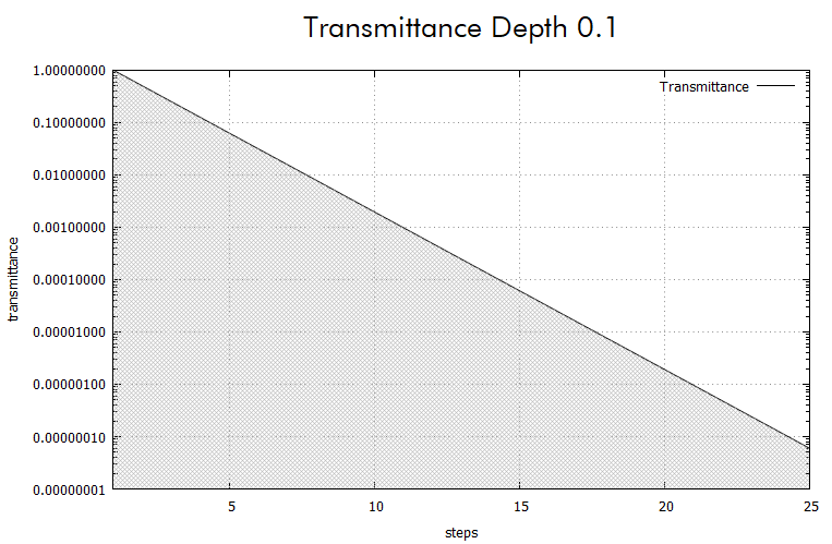
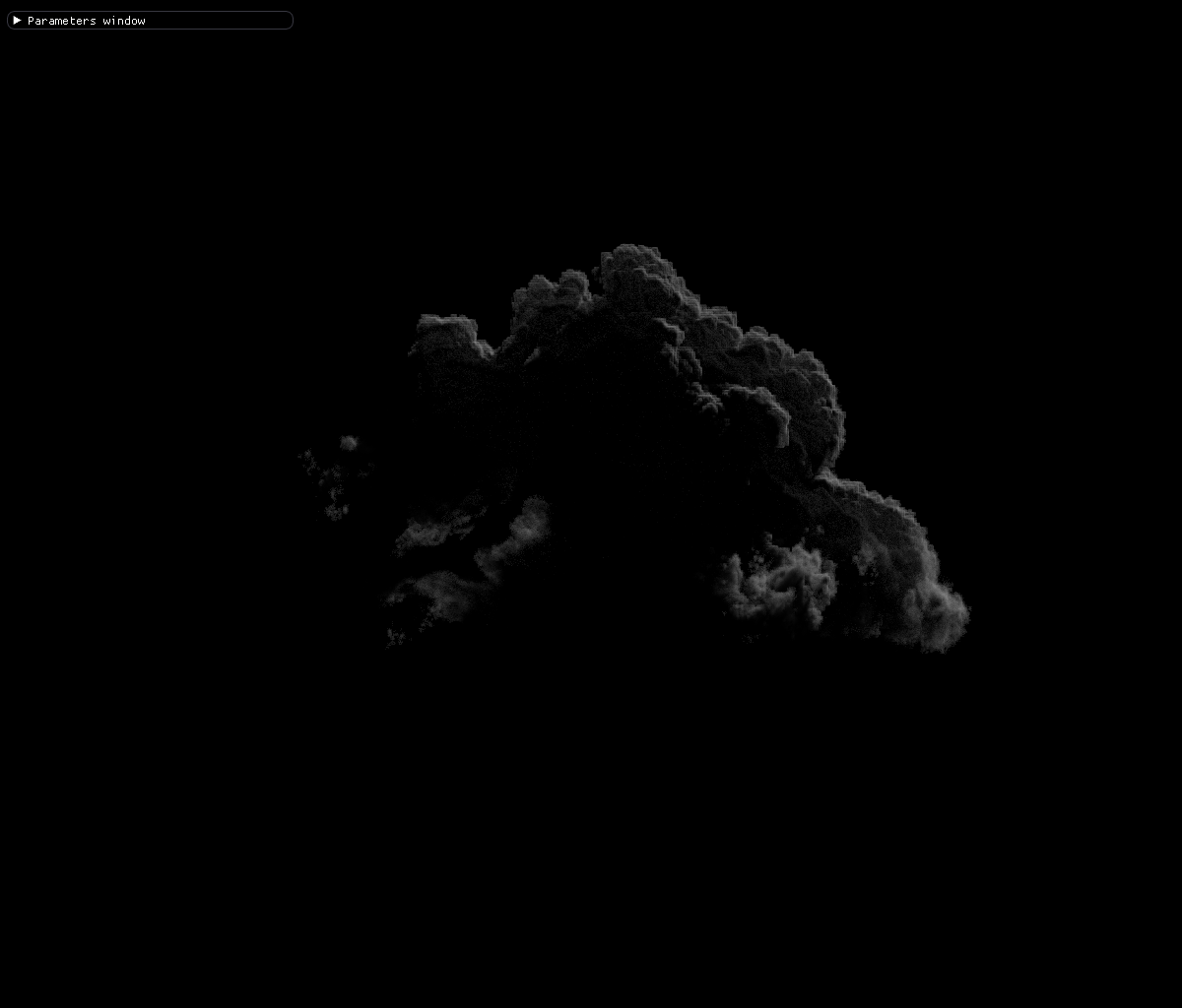
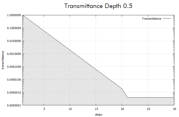
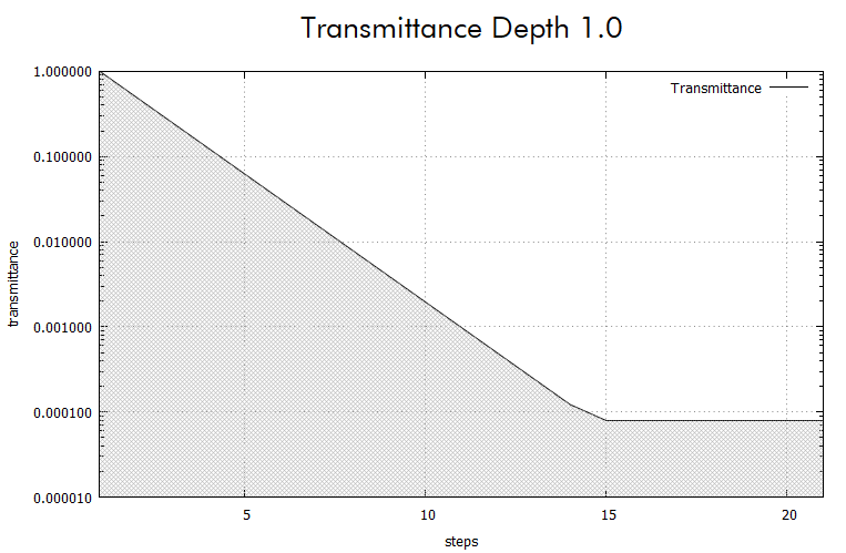

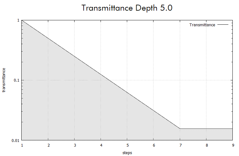
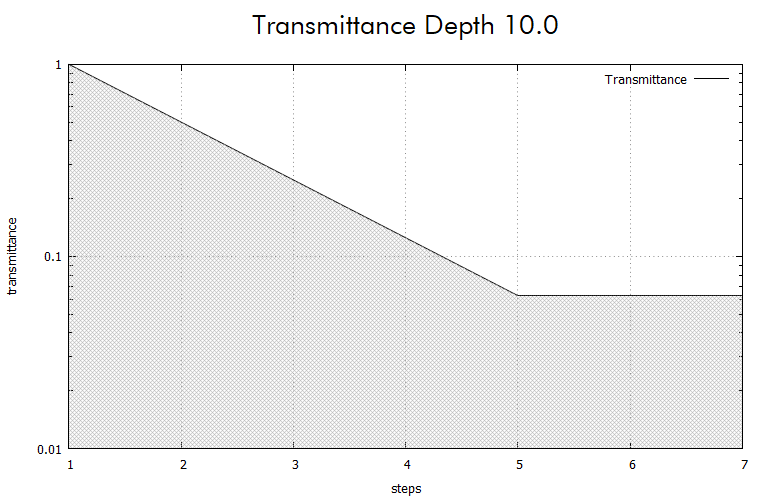
Please note that transmittance values are in log scale
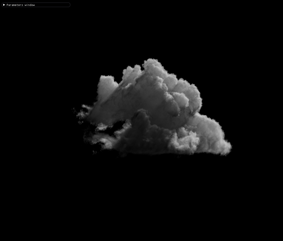
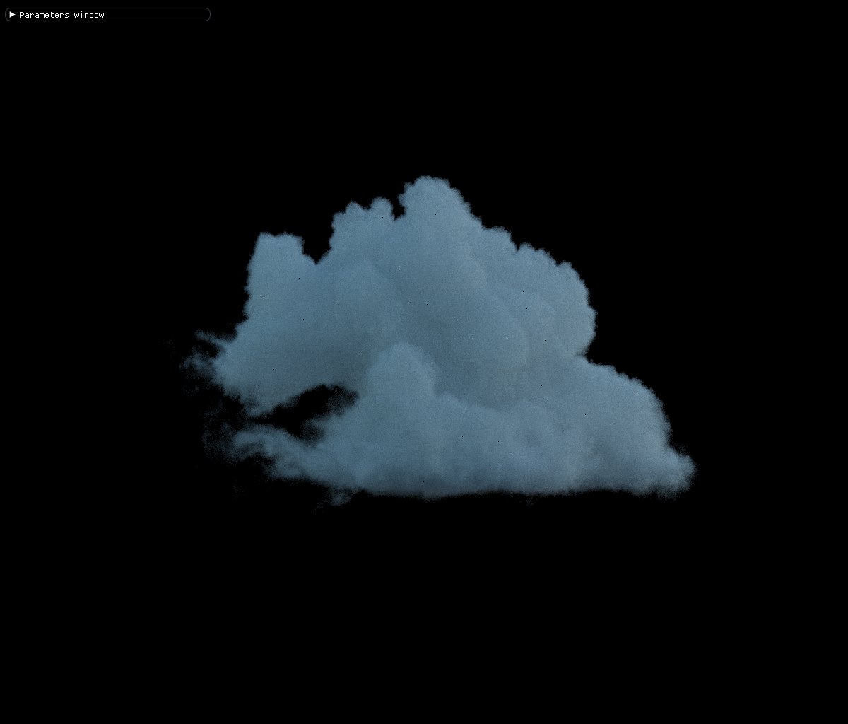 Cloud rendered with sun light only.
100 ray depth, 1000 spp, isotropic phase function ~10m, tr depth 1.0
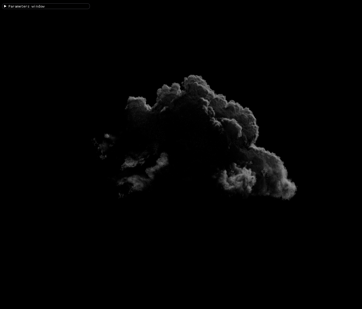
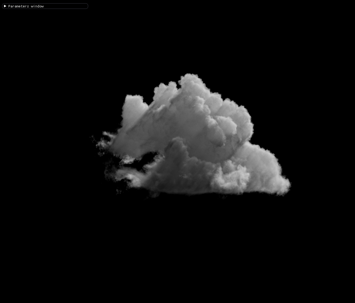
Cloud rendered with sun light only.
100 ray depth, 1000 spp, isotropic phase function ~10m, tr depth 1.0
Pbrt implemets lighting with Light classes but since I have two light types (sun and sky) I’ve decided to implement them in functions. Sun light estimation is based on pbrt’s “Direct Lighting” algorithm.
And since it’s a delta light, multiple importance sampling is very straightforward. We just find the phase function pdf with sun light direction and ray direction, calculate transmittance and multiply all with sun’s power. Since light pdf is always 1.0f, it’s not taken into account.
Multiple importance sampling of environment sky light is a little bit more involved than delta lights (distant and point lights) because it involves calculating lighting from multiple directions and we need to apply MIS for both light and phase functions.
Light multiple importance sampling is implemented based on pbrt but bsdf sampling with MIS required a new function to draw a pdf value based on the techniques provided in “Sampling A Procedural Sky“.
To find a pdf value based on a direction, first I’m converting the cartesian direction to a spherical position of theta and phi. Then I’m calculating the row and column values from the spherical coordinates. Calculating the pdf is then trivial as we covered in last part.
Phase functions in volumetric rendering is the analog of bsdf’s in regular path tracing. It dictates the scattered direction of the incoming ray into an outgoing direction. The most used phase functions in volumetric rendering are Henyey-Greenstein, Rayleigh and Mie phase functions. For my volumetric path tracer I’ve implemented Henyey-Greenstein and a double-Henyey-Greenstein phase functions.
Henyey-Greenstein phase function is first introduced in 1941 and is used to estimate the light direction in participating media. It has an anistropy parameter (often “g” and -1.0<g<1.0) that hints the forward or backward scattering attribute of media. A high (close to 1.0) anisotropy means the light entering the volume scatters mostly in the direction it was coming from. And a low g (close to -1.0) means most of the light scatters back to it’s source. And a 0.0 g means an isotropic medium that scatters light randomly in a unit sphere.
By using a second Henyey-Greenstein phase function one can have the double lobe scattering of the light. It may not be scientifically correct but sometimes necessary for visual aesthetics. But beware it comes with double the heavy calculations involved with sampling phase function and pdfs. I’ve implemented double henyey-greenstein with a general isotropy parameter “f” with f being between 0 and 1 and used this to lerp between directions and pdfs of two henyey-greenstein phase functions.
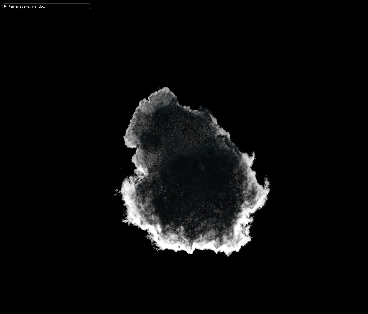
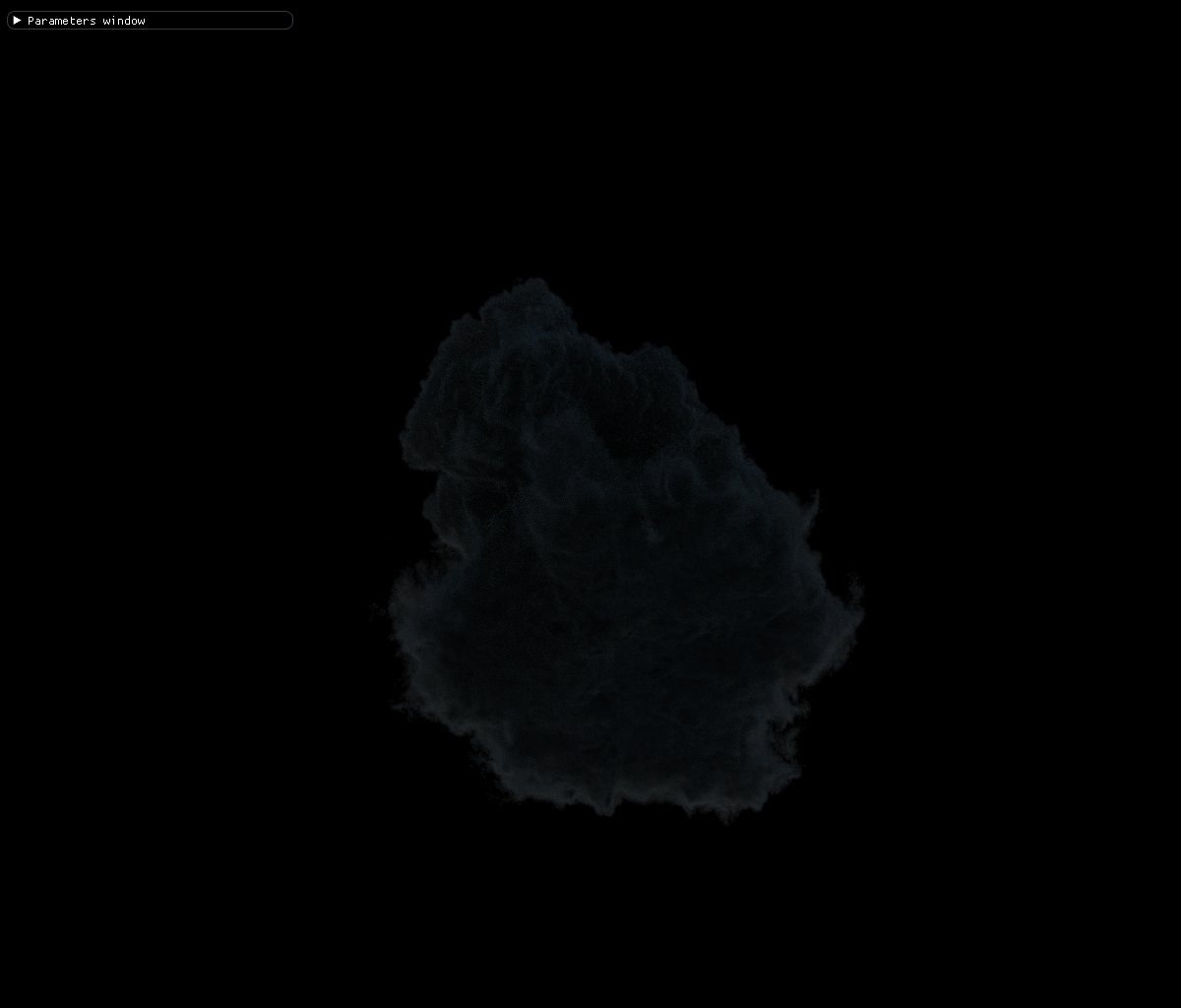
In volumetric rendering phase function is mainly used in lighting calculations and finding a direction to the next path vertex. In lighting calculations phase function is used to weigh the lighting contribution from the light in the ray direction. Below you can see the effect of phase function when the cloud is viewed from the bottom and the sun is directly behind the cloud. A high g value causes very bright edges because most of the light that comes from the sun continues in the direction towards the eye. And with a low g value most of the light bounces back and doesn’t reach the eye.
The other use of phase function is to sample a new direction for the ray which has entered the volume. Right now the the volume rendering in my path tracer can be summed as
Find the first contact with the volume if ray enters bounding box. Sample a length of distance to continue. Sample a light (sun or sky) based on probability of 1/2. Find a new direction for ray based on phase function. The phase function dictates the new direction of the ray when the ray is bouncing inside the volume within a given ray depth. If the phase function is isotropic, the direction is very chaotic. You can see the effect of an isotropic phase function on the ray directions below.
In this 3D visualization, the advancements of 100 rays in volume are shown. The ray depth is set to 1000 and the paths outside volumetric regions are omitted for viewing purposes.
A high g parameter on the other hand causes the ray directions to move relatively in the same direction. The ray directions are less chaotic and they start to cross the volume as a whole. Altough this is the expected behaviour of the clouds, unfortunately it also means more lighting calculations because the ray doesn’t leave the volume easily.
And a very low “g” value causes most of the rays to turn around and leave the volume in the direction they were coming from.
That wraps up the lighting and transmittance part of the volumetric path tracer. In the next part I will be covering how to integrate the Nvidia open vdb library GVDB in to a path tracer and the distance sampling. I will also be talking a little bit about current bugs and future plans.
Until then. Take Care!!!
Building a physically based atmospheric renderer without precomputation
Learn how to install, build and use VPT
Learn how to create a path tracer using houdini particles